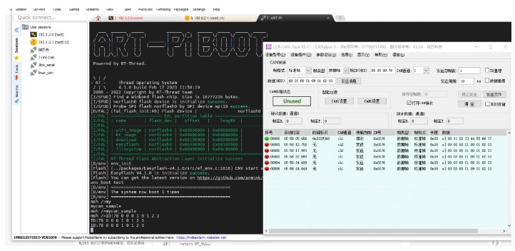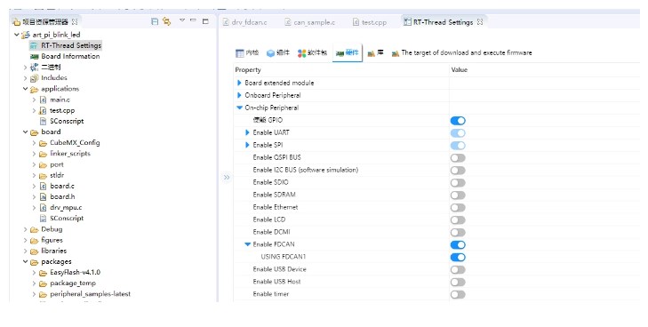
为了调整通信线路的性能和适应性,您需要对波特率设置进行相应的修改。这一过程旨在确保数据传输的速度与设备兼容性达到最优化状态。具体操作通常涉及进入系统的配置界面或者直接通过硬件接口进行调整,选择合适的波特率值以匹配您的应用需求或通信协议标准。该步骤对于确保数据在不同设备间高效、无误地交换至关重要,有助于提升整体的系统稳定性和通信效率。
调校时间设定,以确保可以将输入时钟频率调整至80兆赫兹,如您所见。

修改drv_fdcan.c文件,由于本文使用的是500K的波特率,故只改了一小部分。
static const _stm32_fdcan_NTconfig_t st_CanNTconfig[]=
/
baud brp sjw tseg1 tseg2
/
{
{CAN1MBaud, 1,8,63,16},
{CAN800kBaud, 10,8,20,4},
{CAN500kBaud, 2,8,63,16},
{CAN250kBaud, 20,8,35,4},
{CAN125kBaud, 40,8,35,4},
{CAN100kBaud, 40,8,44,5},
{CAN50kBaud, 80,8,44,5},
{CAN20kBaud, 200,8,44,5},
{CAN10kBaud, 400,8,44,5}
};
修改drv_fdcan.c文件下的FDCAN_MODE_INTERNAL_LOOPBACK,改为FDCAN_MODE_EXTERNAL_LOOPBACK;此项改动为防止FDCAN在回环模式下TX没有输出信号;
static rt_err_t _inline_can_config
{
_stm32_fdcan_t *pdrv_can;
rt_uint32_t tmp_u32Index;
RT_ASSERT;
RT_ASSERT;
pdrv_can = can->parent.user_data;
RT_ASSERT;
pdrv_can->fdcanHandle.Init.FrameFormat = FDCAN_FRAME_CLASSIC;
pdrv_can->fdcanHandle.Init.Mode = FDCAN_MODE_NORMAL;
pdrv_can->fdcanHandle.Init.AutoRetransmission = DISABLE;
pdrv_can->fdcanHandle.Init.TransmitPause = DISABLE;
pdrv_can->fdcanHandle.Init.ProtocolException = DISABLE;
switch
{
case RT_CAN_MODE_NORMAL:
pdrv_can->fdcanHandle.Init.Mode = FDCAN_MODE_NORMAL;
break;
case RT_CAN_MODE_LISEN:
pdrv_can->fdcanHandle.Init.Mode = FDCAN_MODE_BUS_MONITORING;
break;
case RT_CAN_MODE_LOOPBACK:
pdrv_can->fdcanHandle.Init.Mode = FDCAN_MODE_EXTERNAL_LOOPBACK;
break;
default:
pdrv_can->fdcanHandle.Init.Mode = FDCAN_MODE_NORMAL;
break;
}
/
config baud rate
/
tmp_u32Index = _inline_get_NTbaud_index;
pdrv_can->fdcanHandle.Init.NominalPrescaler = st_CanNTconfig[tmp_u32Index].u16Nbrp;
pdrv_can->fdcanHandle.Init.NominalSyncJumpWidth = st_CanNTconfig[tmp_u32Index].u8Nsjw;
pdrv_can->fdcanHandle.Init.NominalTimeSeg1 = st_CanNTconfig[tmp_u32Index].u8Ntseg1;
pdrv_can->fdcanHandle.Init.NominalTimeSeg2 = st_CanNTconfig[tmp_u32Index].u8Ntseg2;
if
{
pdrv_can->fdcanHandle.Init.MessageRAMOffset = 0;
}
else
{
pdrv_can->fdcanHandle.Init.MessageRAMOffset = 1280;
}
pdrv_can->fdcanHandle.Init.StdFiltersNbr = 2;
pdrv_can->fdcanHandle.Init.ExtFiltersNbr = 2;
pdrv_can->fdcanHandle.Init.RxFifo0ElmtsNbr = 1;
pdrv_can->fdcanHandle.Init.RxFifo0ElmtSize = FDCAN_DATA_BYTES_8;
pdrv_can->fdcanHandle.Init.RxBuffersNbr = 0;
pdrv_can->fdcanHandle.Init.TxEventsNbr = 0;
pdrv_can->fdcanHandle.Init.TxBuffersNbr = 3;
pdrv_can->fdcanHandle.Init.TxFifoQueueElmtsNbr = 0;
pdrv_can->fdcanHandle.Init.TxFifoQueueMode = FDCAN_TX_FIFO_OPERATION;
pdrv_can->fdcanHandle.Init.TxElmtSize = FDCAN_DATA_BYTES_8;
if != HAL_OK)
{
return -RT_ERROR;
}
/
default filter config
/
HAL_FDCAN_ConfigFilter;
/
init fdcan tx header
/
_inline_can_tx_header_init;
/
can start */
HAL_FDCAN_Start;
return RT_EOK;
}

2.添加完成后,查看can_sample.c文件,如下图所示;

为了对 `can_sample.c` 文件进行修订,我首先将目标聚焦于替换现有的 CAN 设备标识符,并新增配置 CAN 波特率的代码段落,以确保整个系统在运行时能够正确地识别和操作所指定的设备,并且可以按照预期速度进行数据传输。以下是经过优化、改写后的代码片段:
c
#include
// 假设这里包含了所有必要的头文件,用于 CAN 通信设置
void setup_can1_fd {
// 初始化 CAN 设备 fdcan1 的配置参数
int can_device = fdcan1; // 替换实际的设备句柄定义或获取方式
// 设置 CAN 接口参数,包括波特率、位格式等
// 示例代码:假设通过函数 `configure_can_interface` 进行配置操作
configure_can_interface; // 将波特率设置为 500kbps
// 验证设备初始化和配置状态
if == true) {
printf;
} else {
printf;
}
}
int main {
// 示例代码:初始化和开始 CAN 通信流程
setup_can1_fd;
// 进行后续的程序操作,如数据发送、接收等
return 0;
}
这段修订后的代码示例性地展示了如何将设备名从 `can1` 更改为 `fdcan1`,并通过一个假设的函数 `configure_can_interface` 来设置 CAN 波特率。请根据实际的硬件和软件环境调整相关的设备句柄获取方式、配置函数及波特率值。
在实际应用中,请确保遵循正确的编程规范,并对具体环境中的 API 调用进行相应的适配,因为具体的库函数和变量命名可能会因不同系统和库而有所不同。
#include
#include
#define CAN_DEV_NAME "fdcan1" /* CAN 设备名称
/
static struct rt_semaphore rx_sem; /
用于接收消息的信号量
/
static rt_device_t can_dev; /
CAN 设备句柄
/
/
接收数据回调函数
/
static rt_err_t can_rx_call
{
/
CAN 接收到数据后产生中断,调用此回调函数,然后发送接收信号量 */
rt_sem_release;
return RT_EOK;
}
static void can_rx_thread
{
int i;
rt_err_t res;
struct rt_can_msg rxmsg = {0};
/
设置接收回调函数
/
rt_device_set_rx_indicate;
#ifdef RT_CAN_USING_HDR
struct rt_can_filter_item items[5] =
{
RT_CAN_FILTER_ITEM_INIT, /
std,match ID:0x100
0x1ff,hdr 为 - 1,设置默认过滤表
/
RT_CAN_FILTER_ITEM_INIT, /
std,match ID:0x300
0x3ff,hdr 为 - 1
/
RT_CAN_FILTER_ITEM_INIT, /
std,match ID:0x211,hdr 为 - 1
/
RT_CAN_FILTER_STD_INIT, /
std,match ID:0x486,hdr 为 - 1
/
{0x555, 0, 0, 0, 0x7ff, 7,} /
std,match ID:0x555,hdr 为 7,指定设置 7 号过滤表
/
};
struct rt_can_filter_config cfg = {5, 1, items}; /
一共有 5 个过滤表
/
/
设置硬件过滤表
/
res = rt_device_control;
RT_ASSERT;
#endif
while
{
/
hdr 值为 - 1,表示直接从 uselist 链表读取数据
/
rxmsg.hdr = -1;
/
阻塞等待接收信号量
/
rt_sem_take;
/
从 CAN 读取一帧数据
/
rt_device_read);
/
打印数据 ID 及内容
/
rt_kprintf;
for
{
rt_kprintf;
}
rt_kprintf;
}
}
int mycan_sample
{
struct rt_can_msg msg = {0};
rt_err_t res;
rt_size_t size;
rt_thread_t thread;
char can_name[RT_NAME_MAX];
if
{
rt_strncpy;
}
else
{
rt_strncpy;
}
/
查找 CAN 设备
/
can_dev = rt_device_find;
if
{
rt_kprintf;
return RT_ERROR;
}
/
初始化 CAN 接收信号量
/
rt_sem_init;
/
以中断接收及发送方式打开 CAN 设备
/
res = rt_device_open;
RT_ASSERT;
/
设置 CAN 通信的波特率为 500kbit/s
/
res = rt_device_controlCAN500kBaud);
RT_ASSERT;
/
创建数据接收线程
/
thread = rt_thread_create;
if
{
rt_thread_startup;
}
else
{
rt_kprintf;
}
msg.id = 0x78; /
ID 为 0x78
/
msg.ide = RT_CAN_STDID; /
标准格式
/
msg.rtr = RT_CAN_DTR; /
数据帧
/
msg.len = 8; /
数据长度为 8
/
/
待发送的 8 字节数据
/
msg.data[0] = 0x00;
msg.data[1] = 0x11;
msg.data[2] = 0x22;
msg.data[3] = 0x33;
msg.data[4] = 0x44;
msg.data[5] = 0x55;
msg.data[6] = 0x66;
msg.data[7] = 0x77;
/
发送一帧 CAN 数据
/
size = rt_device_write);
if
{
rt_kprintf;
}
return res;
}
/
导出到 msh 命令列表中 */
MSH_CMD_EXPORT;
